The
Note:
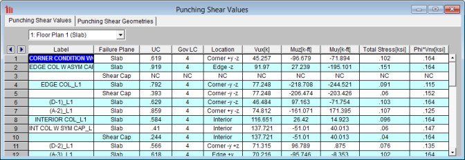
This section reports the basic / summary data for the punching shear code check.
This gives the designation between the slab punching shear check and the shear cap. If there is a shear cap present then the punching shear check will always show both failure planes. If there is no shear cap then you will only have a single slab shear check.
The UC value is the governing code check (Total Stress /phi*Vnx) for the pedestal punching shear. The Gov LC value is the Load combination that resulted in this maximum code check.
The pedestal and slab geometry is investigated and checked for all three types of punching failure (Interior, Edge and Corner). This field represents the type of failure method that controlled the code check calculation for the given pedestal.
This value represents the factored load transferred from the pedestal into the slab for the governing load combination. This corresponds to the axial force in the Column
These values represent the factored moments about the local axes of the Column.
The Total Stress is the direct shear stress plus the shear stress due to moment. For more information, see the Punching Shear - Design topic.
This represents the shear stress capacity of the slab calculated based on the three ACI equations for two way or punching shear capacity of the slab. Refer to ACI 318-14 Section 22.6.5 (ACI 318-11 Section 11.11.7.2) for more information. When ACI 318-19 is selected, the shear strength of concrete (Vc) uses equations in Table 22.6.5.2. Note that an additional size effect factor λs is added in the equation, λs is a function of effective depth of the slab d, and is calculated per Equation (22.5.5.1.3).
Note:
Minimum Slab Reinforcement at Punching Shear Critical Section
ACI 318-19 requires a minimum slab reinforcement at punching shear critical section if vuv>φ2λφ√f’c per Section 8.6.1.2. The As,min is calculated and presented in the punching shear result of columns under this condition. Please note that the reinforcement design in elevated slabs does not consider this requirement, users need to adjust the slab reinforcement at punching shear critical section to account for this code requirement. RISA provides the calculations of As,min per Equation (8.6.1.2) in the Detail Report

Note:
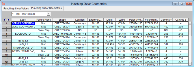
The pedestal and slab geometry is investigated and checked for all three types of punching failure (Interior, Edge and Corner). This field represents the type of failure method that controlled the code check calculation for the given pedestal.
The effective depth of the slab is used to define the punching shear perimeter at a distance of d/2 beyond the edge of the pedestal.
Length of the critical section along the local axes.
Note:
This is a property (Jc) of the critical section which is analogous to polar moment of inertia about the longitudinal column/pedestal axes.
This is calculated from the dimensions of the assumed punching shear perimeter. It represents the fraction of the unbalanced moment for each axis that is transferred by eccentricity of shear.
Note:
 - This button will allow you to take a snapshot of the current detail report you are viewing so that it can be added to a report. View the Printing topic for more information.

The input echo lists off the column label, floor, column shape, slab material, slab thickness, column location, cover, design rule and design code. The graphic view shows the dimensions used in the calculations. The graphics shown above shows the punching shear information when a shear cap is present. If there is no shear cap (or the dimensions of the cap violate the ACI code requirements and the cap is ignored) then the diagram will be much simpler.
Note:
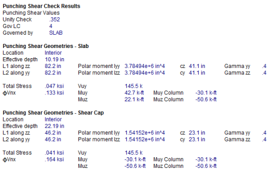
The Unity Check gives a ratio of demand to capacity, while the Gov LC gives the load combination that produced this maximum unity check.
For an explanation of the rest of these values see both the spreadsheet result explanations above, as well as the Punching Shear - Design topic.